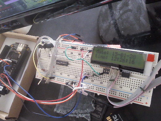
Sample code for using ST7032I I2C/SMBus driver in Midas LCD with python
I'm using Midas MCCOG21605C6W-SPTLYI 2x16 chars LCD panel, connected to 5V VDD and 3.3V BeagleBone Black I2C bus:

Code for the above LCD clock "app" (python 2.7):
import smbus, time

class ST7032I(object):

  def __init__(self, addr, i2c_chan, **init_kws):
    self.addr, self.bus = addr, smbus.SMBus(i2c_chan)
    self.init(**init_kws)

  def _write(self, data, cmd=0, delay=None):
    self.bus.write_i2c_block_data(self.addr, cmd, list(data))
    if delay: time.sleep(delay)

  def init(self, contrast=0x10, icon=False, booster=False):
    assert contrast < 0x40 # 6 bits only, probably not used on most lcds
    pic_high = 0b0111 << 4 | (contrast & 0x0f) # c3 c2 c1 c0
    pic_low = ( 0b0101 << 4 |
      icon << 3 | booster << 2 | ((contrast >> 4) & 0x03) ) # c5 c4
    self._write([0x38, 0x39, 0x14, pic_high, pic_low, 0x6c], delay=0.01)
    self._write([0x0c, 0x01, 0x06], delay=0.01)

  def move(self, row=0, col=0):
    assert 0 <= row <= 1 and 0 <= col <= 15, [row, col]
    self._write([0b1000 << 4 | (0x40 * row + col)])

  def addstr(self, chars, pos=None):
    if pos is not None:
      row, col = (pos, 0) if isinstance(pos, int) else pos
      self.move(row, col)
    self._write(map(ord, chars), cmd=0x40)

  def clear(self):
    self._write([0x01])

if __name__ == '__main__':
  lcd = ST7032I(0x3e, 2)
  while True:
    ts_tuple = time.localtime()
    lcd.clear()
    lcd.addstr(time.strftime('date: %y-%m-%d', ts_tuple), 0)
    lcd.addstr(time.strftime('time: %H:%M:%S', ts_tuple), 1)
    time.sleep(1)
Even with the same exact display, but connected to 3.3V, these numbers should probably be a bit different - check the datasheet (e.g. page-7 there).
Also note the "addr" and "i2c_chan" values (0x3E and 2) - these should be taken from the board itself.
And the address is easy to get from the datasheet (lcd I have uses only one static slave address), or detect via i2cdetect -r -y <i2c_chan>, e.g.:
# i2cdetect -r -y 2
     0  1  2  3  4  5  6  7  8  9  a  b  c  d  e  f
00:          -- -- -- -- -- -- -- -- -- -- -- -- --
10: -- -- -- -- -- -- -- -- -- -- -- -- -- -- -- --
20: -- -- -- -- -- -- -- -- -- -- -- -- -- -- -- --
30: -- -- -- -- -- -- -- -- -- -- -- -- -- -- 3e --
40: -- -- -- -- -- -- -- -- -- -- -- -- -- -- -- --
50: -- -- -- -- UU UU UU UU -- -- -- -- -- -- -- --
60: -- -- -- -- -- -- -- -- 68 -- -- -- -- -- -- --
70: -- -- -- -- -- -- -- --
Here I have DS1307 RTC on 0x68 and an LCD panel on 0x3E address (again, also specified in the datasheet).
Plugging these bus number and the address for your particular hardware into the script above and maybe adjusting the values there for your lcd panel modes should make the clock show up and tick every second.
In general, upon seeing tutorial on some random blog (like this one), please take it with a grain of salt, because it's highly likely that it was written by a fairly incompetent person (like me), since engineers who deal with these things every day don't see above steps as any kind of accomplishment - it's a boring no-brainer routine for them, and they aren't likely to even think about it, much less write tutorials on it (all trivial and obvious, after all).
Nevertheless, hope this post might be useful to someone as a pointer on where to look to get such device started, if nothing else.